 strumenti e misuregeotecniche e strutturali
In-Place Inclinometer
Specifications
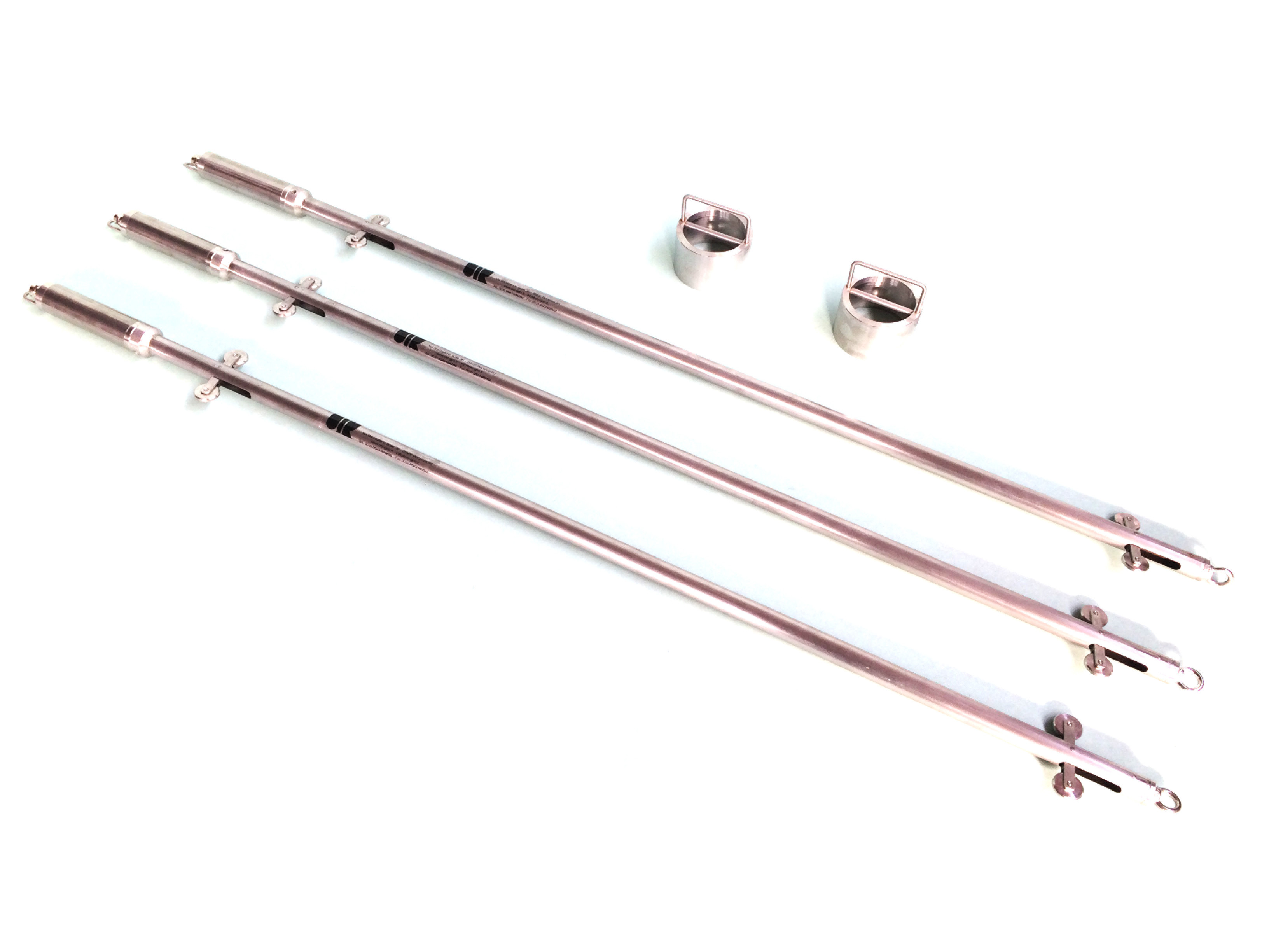
In case of: landslides and unstable areas; rock masses and walls; tunnels and underground works; diaphragrams and retaining walls, earth and concrete dams and foundation piles; OTR suggest OG310F in-place inclinometer. In-place inclinometer is constituted by a stainless steel body in which is mounted a biaxial or uniaxial sensor. The instrument is equipped with two pairs of opposite wheels which allows inclinometer to follow movement. The distance between the pairs of wheels is 1000mm. The sensor of the probe is a mems-type sensors that ensure high robustness with strokes (for exemple due to possible repositioning in different holes and depths). The sensors are seaked in epoxy resin and resist in high pressure conditions. The full scale of ±15° or ±30° allows a measurement resolution and stability appropriate to the normal conditions of use. Measurements can be executed by a portable readout unit or by datalogger placed on the top of the casing. If the management of the measures is automatic OTR has specific software that allows a real-time monitoring and a relative activation of warning thresholds.
How does the instrumentation be installed?
After having checked positioning quotes of the in-place inclinometer, using a removable inclinometer, fix every probe to its own probe’s top cap at the extablished depth. A steel wire connected to the cap of probe make it possible to lower the inclinometer into borehole and suspend it at the proper castor wheels.
To instal the probe, it’s advised to acquire the following materials: (which can be provided by OTR as accessories): top cap, steel wire (1.5 mm in diameter), and fastening clamps.
In order to install the instrument, proceed as follows:
Cut a length of steel wire equal to the installation depth (+ 20 cm) of the first in-place probe (the one that is installed deeper down). Tie the cable in a loop around the suspension ring which is welded to the sensor cylinder. Tie the steel wire with a fastening clamp;
Starting from the instrument, unwind the electrical cable and tape it to the steel wire every 1 to 2 meters;
Prior to installing the instrument, take a control reading with the readout unit, positioning the instrument at a known angle and checking that the measurement taken by the readout unit is correct;
Insert the in-place probe in the tube aligning the wheels with the groove, then drop the instrument to the selected depth using the steel wire;
Route the steel wire at the center of the tube welded on the top cap. Create a loop in the cable, and clamp it with a fastening clamp after the in-place probe has reached the selected depth;
Route the electrical cable over the top cap for the following wiring;
Repeat all the steps above for all the in-place probes to be installed in the tube;
After the installation has been completed, take some control measurements and write down the obtained values.
In case the instruments are removed, either for maintenance or to take measurements with a removable probe, remember taking measurements before and after repositioning the probes, so as to process data correctly.

Sede Legale
Galleria San Donnino, 4
Piacenza 29121
P.IVA/CF 00894610153
Sede operativa
Amministrazione
Direzione Commerciale
+39 347 2602151
Dott. Eligio Degli Angeli
vendite@otr-geo.it
Francesco Morgante